STEAM
OPERATIONS
OF THE
CHESAPEAKE &OHIO RAILWAY
AT
by
William E. Simonton, III
| Home | Steam Operations | Drawings |
Typical Heavyweight Passenger Car
Consists 1940's | Contact |
| Numbered Structures | A.F.E. Map Revisions | Articles | Notes | Things to Come | What's New | Photos |
Last Updated: 7-29-2019
[ Roundhouse ] [ Mallet Engine House ] [ Coal Dock ] [ Sand Bunker ] [ Pit Structures ] [ Trackside Shanties ] [ C & O Drawings ] [ HAER Drawings ] [ Miscellaneous Drawings ] [ Freight Depot ] [ Passenger Station ]
The drawings were prepared using any official C & O
drawings available from the Chesapeake & Ohio
Historical Society, Inc., on-site measurements, and photographs. All
are in 1/4" scale and direction is railroad direction. Please
note that as a result of a loop in the New River at Hinton, geographical North
corresponds to railroad South, and geographical East is railroad West. The
drawing typically refer to railroad direction – not geographical direction.
Many were initially prepared starting with Generic CADD® and were subsequently transferred to VISUAL CADD®. CADD files in GENERIC CADD® format, VISUAL CADD® format, AUTOCAD DXF format, and AUTOCAD® format can be made available under terms limiting their reproduction and distribution. I will email the CADD files to any individual interested in closely examining the drawings upon their agreement not to reproduce and/or distribute copies. VISUAL CADD® has a free utility which permits viewing the drawing without purchasing the full CADD program.
The linked Adobe Acrobat® files were printed to file and then distilled using Adobe Acrobat Distiller to architectural size paper in Adobe pdf format prints. You may print them and zoom in if one uses Adobe Acrobat Reader. Adobe Acrobat Reader 5.0 or later is recommended. Here is a link to download the free software Adobe Acrobat Reader. Typical file size is runs from 25K to 104K bytes. Areas which are "Hatched" with "Concrete" do not translate correctly and the hatch displays as a pattern of "+"s.
I will make N, HO, S and O scale copies available in pdf
format upon an agreement not to reproduce and/or distribute copies.
I have concentrated on structures for which The Chesapeake & Ohio Historical Society, Inc. does not have drawings, has only partial drawings, or although it may have the drawings in the archives, they have not been found or indexed.
HINTON YARDS - A pdf scan of C &
O Drawing No. 6281-A which illustrates the Hinton and Avis Yards.
This document was done in four (4) panels as the original drawing is
approximately 32" x 12" at a scale of 1/4" = 100'. Page 1
starts at the left and are arranged 1, 2, 3 & 4 horizontally. The
drawing was revised to 1978, and therefore all track changes and structures
removed prior to 1978 are reflected in the drawing. A larger scale drawing
(1" = 200') of the Hinton and Avis Yards circa 1946 may be obtained from
the C & O Historical Society - Drawing No. 6281 (Note no
"A") which is approximately 24" x 110".
HINTON COAL DOCK DRAWINGS -- AS REBUILT 1946 Notes 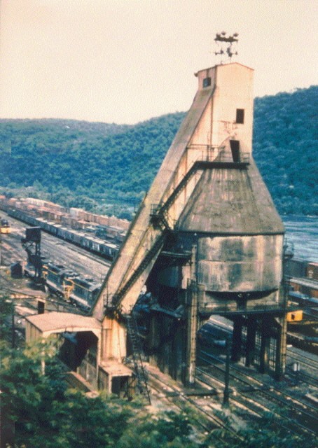
1. 800 Ton Fairbanks Morse Coal Dock R.R. East Elevation
2. 800 Ton Fairbanks Morse Coal Dock R.R. West Elevation
3. 800 Ton Fairbanks Morse Coal Dock R.R. North Elevation
4. 800 Ton Fairbanks Morse Coal Dock R.R. South Elevation
5. 800 Ton Fairbanks Morse Coal Dock Sections
6. Fairbanks Morse Coal Dock Coal Dock Plan (Hinton)
7. Coal Dock Foreman’s Office, Locker & Toilet
8. Coal Dock Pit Construction Details (from Fairbanks Morse drawings)
9. Interior Details of Monitor (from
Fairbanks-Morse drawing).
10. 3D Drawing of Fairbanks Morse Co. 800 Ton Coal Dock Concrete structure of Coal Dock. Solid Outline works best for viewing in Adobe Acrobat or Acrobat Reader. Browser pdf viewrs will not work in 3D. Click on drawing to activate 3D mode. (WORK IN PROGRESS)
HINTON CHESSIE M-1 COAL DOCK DRAWINGS
1. William Sparkmon's Drawings & Notes on the Chessie Coal Docks Note.
2. M1 Coal Dock East & North Elevations (WORK IN PROGRESS)
3. M1 Coal Dock West & South Elevations (WORK IN PROGRESS)
C & O 800 Ton Fairbanks Morse
Coal Docks
Stevens, Kentucky – Elevated Hoist House & Additional Internal Coal Bin, and
Coaling Chutes.
a)
North Elevation (similar to Hinton R.R. East)
b) East Elevation (similar to Hinton R.R. South)
c)
West Elevation (similar to Hinton R.R. North)
d) South Elevation (similar to
Hinton R.R. West)
Fulton Yard,
Richmond, Virginia
– Straight Hoist Shaft and modified Hoist House.
a) North Elevation (similar to Hinton R.R. East)
b) East Elevation (similar to
Hinton R.R. South)
c) West Elevation (similar to Hinton R.R. North)
d) South
Elevation (similar to Hinton R.R. West)
HINTON SAND BUNKER
1. 200 Ton Fairbanks Morse Sand
Bunker (2 elevations)
2. 200 Ton Fairbanks Morse Sand Bunker (2 elevations)
1. Three track Fairbanks Morse 60 Cu.Ft. Universal Cinder Conveyer (Mellin Patent)(After 1943) (WORK IN PROGRESS)
Chillingsworth Air Operated Cinder Hoist - Not used at Hinton (used at Richmond), but the details of the cinder hoist provide engineering details of the size and weight of steel used and particularly of the dumping mechanism which was used on "Universal" cinder conveyors manufactured by Fairbanks-Morse, Ogle, and Roberts & Shaefer, and should
be helpful to any modeler attempting to build a "Universal" cinder conveyor.
See April 2007 issue of the C & O Historical Magazine for photos of Gladstone.

2. Fire Hose House Building 70
3. Arch Brick Storage House Building 88 (WORK IN PROGRESS)
4. D & M Pump House Building 100 Part of the Engine Wash Rack System
5. Ash Pan Thawing Devices (scanned from C & O Drawing)
7. a) Wash Rack Sections as rebuilt circa 1947 (Complete except for D&M Wash Machine & pipes)
b) Wash Rack Plan View as rebuilt circa 1947 with Grids Installed & D & M Pump House
c) D&M Wash Machine Arrangement. (WORK IN PROGRESS) (Early partial draft).
8. Hostler's Shanty Building #103
9. Bethlehem 115' Twin Span Turntable & Turntable Pit (WORK IN PROGRESS) (Note)
The Robertson was located just west of the Ice House and was removed in 1943.
11. Coal House Building 83 (WORK IN PROGRESS)
12. Assist. Yard Foreman's Office Bldg 51. Later became the Grand Central Yard Office.
14. Engine Supply House Building 86.
16. Electric Pump House Building 35
18. Water Treatment Plant Building 99 (WORK IN PROGRESS)


1. Tool House Section 122 Note
2. Hostler’s & Passenger Car Equipment
House
3. Switchmen’s Shanty Building 27
4. Signal & Water Supply House Building 28
5. Motor Car House No. 1 Building 29
6. Ice House & Icing Platform Building 30 Ice
House
7.
8. Engine Yard Laborer’s Shanty
Building 31
9. Linemen’s Tool House Building 106 Note
10. Propane Gas Storage House Building 108
Note
11. Inspection Motor Car House Building 109
13. Scale House Building 33 - WORK IN PROGRESS
HINTON ROUNDHOUSE Roundhouse
Article (1905-1980)
1. Plan View Circa 1905-1910 Updated 5/14/2007
a. "As Built" End Walls and Rear Panel Elevation (typical) drawings.
b. End Walls and Rear Panel Elevation (typical) drawings
after monitor roof was added (before 1916).
2.
Plan Circa 1916
a. End Wall and Rear Panel Elevations (typical)
b. Section through typical stall (12 thru 17).
a. Section through typical stall (5 thru 11)
b. Rear Panel Elevations (1930)
d. R.R.
e. The Chesapeake
& Ohio Historical Society, Inc. has drawings of the 1928-29 addition.
a. End Wall at Stall 17 and Rear Panel Elevations
b. Section through Stall 16, Roundhouse Office, End Wall Stall 14
e. The Chesapeake & Ohio Historical Society, Inc.
has drawing of the 1942 addition.
a.
Firewall Addition of 1946 with existing firewall.
b.
Profile of Doors and extended stalls 1 thru 13.
6.
Plan Circa 1953 (Incomplete)
MALLET ENGINE HOUSE - Notes
on Mallet Engine House Drawings

COHS
#1403 (1947) Used with permission.
1. Framing Drawings As Built (1911-1942). Includes Plan View.
2. Exterior Elevations As Built (1911-1942). With drawings of various Monitors
used.
3. Framing Drawings As Modified (1942-1959). Includes Plan View.
4. Exterior Elevations As
Modified (1942-1959).
5. Mallet Engine House
Situation Plan - Scanned from
C & O Drawing.
6. Store Room addition to
Mallet Engine House (Bldg. 75).
C & O FREIGHT DEPOT
- Present Day - Drawn by Bryson VanNostrand, AIA
(Used with permission)
6. Shed over 492' x 8' Loading Platform (C & O Drawing)
7. Hinton Freight Depot
Area Plan (Drawn by W. E. Simonton III)
8. Hinton Freight Depot
Pedestrian Bridge Location (Drawn by W. E. Simonton III)
1.
Early Wood Passenger Station Design (SECOND
PASSENGER STATION?)
2. Early Wood Passenger Station Plan WORK IN PROGRESS
3. Brick Passenger Station
"As Built" 1892. (THIRD PASSENGER STATION)
4. Brick Passenger Station Plan WORK IN PROGRESS
5. Hinton Depot (Set 1) (FINAL PASSENGER STATION APPEARANCE) HAER DRAWINGS
1.92 MB circa
1980
6. Hinton Depot (Set 2) (FINAL PASSENGER STATION APPEARANCE) HAER
DRAWINGS 1.13 MB circa 1980 Note
CABINS AT HINTON
CW CABIN Controlled the entrance into the west side of the Hinton Yards
leading to the New River Subdivision
1. Standard two-story wood Cabin until 1942.
2.
Unique single-story Cabin built in 1942 and located 1/3rd mile east of former
location
C & O DRAWINGS (Referenced or linked on this website)
1.
Tail Tracks added
to turntable 1942. Scanned from C & O Drawing.
2. Wood Partition between Stalls
11 & 12 C & O Dwg X-2708. Scanned C & O Drawing
3. Ash Pan Thawing Devices. Scanned from C & O Drawing.
4. Universal Cinder Conveyor Scanned from C & O Drawing.
5. Roundhouse Door Extensions Scanned C & O Drawing
6. Fire Hose House - At Freight
Platform Above Roundhouse - Scanned C & O Drawing
7. Scale House Bldg # 33 - Standard C
& O Scale House used at Hinton Dwg. No. S-308
1. West Yard Hinton
1.82 MB (Incorrect railroad west of Roundhouse) See Hinton Yard pdf above. Note
2. Hinton Depot (Set 1)
1.92 MB
3. Hinton Depot (Set 2)
1.13 MB
1. Robertson Cinder Conveyor (SS Limited)
2. RO-WAY Overhead Door Details (1942
Roundhouse Extension) Scanned Document